
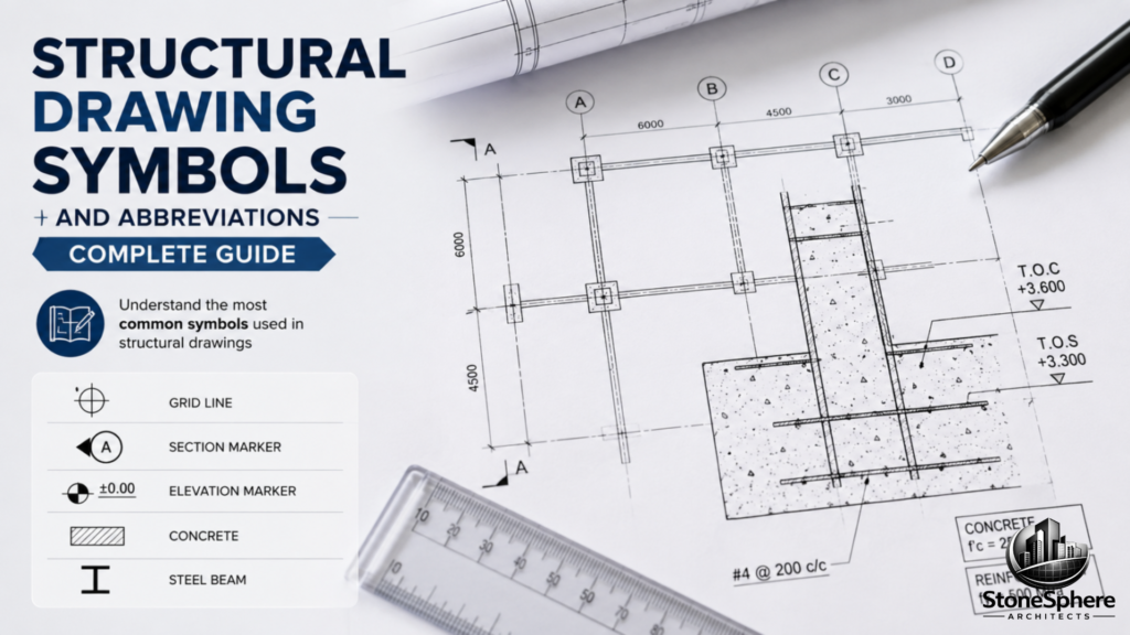
Opening a structural sheet and seeing labels like “TOS,” “CIP,” or “#4 @ 200” can stop even experienced contractors in their tracks if the legend isn’t handy. Misreading a single abbreviation can lead to the wrong bar size, a missed connection detail, or a costly on-site correction. The short answer: structural drawing symbols and abbreviations follow standardized conventions for materials, dimensions, and components, and once you learn the core set, most sheets become easy to decode. This guide breaks down the most common structural drawing symbols, what they mean, and how to read them correctly. Keep reading for a full reference you can use on your next project.
Why Structural Drawing Symbols Matter
Every drawing set relies on structural drawing symbols to communicate detailed information without cluttering the sheet with long text. A single symbol can represent a material, a dimension, or a specific construction requirement in a compact, standardized way.
Misreading these symbols is one of the most common causes of on-site errors, since a small mark or abbreviation can change the meaning of an entire detail. Learning to read structural drawing symbols correctly protects both safety and budget on every project, large or small.
Common Structural Abbreviations
Many structural drawing symbols appear as short abbreviations rather than graphic marks. These shorthand terms save space while keeping meaning precise across the entire set.
Some of the most frequently used abbreviations include:
- BM – Beam
- COL – Column
- FTG – Footing
- CONC – Concrete
- REINF – Reinforcement
- CLR – Clear cover
- EL – Elevation
- TYP – Typical
- TOS – Top of steel
- TOC – Top of concrete
- CIP – Cast-in-place
- SOG – Slab on grade
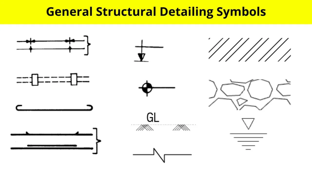
image of civilengineeringweb.com
Reinforcement Symbols and Bar Callouts
Reinforcement details rely heavily on structural drawing symbols to describe bar size, spacing, and quantity in a compact format. A typical callout might read “#4 @ 200,” meaning a number 4 bar spaced at 200 millimeters center-to-center.
Other reinforcement symbols include a circle with a diagonal line for a plain round bar and a hash mark for a deformed bar. Always check the legend, since spacing notation can vary slightly between projects and regions.
Material Symbols on Structural Plans
Material symbols are among the most visual structural drawing symbols, using hatching patterns to represent different substances within a cross-section or detail.
- Diagonal lines typically represent brick or masonry.
- Small dots usually indicate concrete.
- Cross-hatching often shows steel in section.
- Wavy lines may represent insulation material.
These patterns let engineers show multiple materials clearly within a single detail drawing without adding excessive text.
Structural Steel Symbols and Shape Designations
Steel members carry their own set of structural drawing symbols, since shapes and connections need precise identification on framing plans.
Common steel designations include:
- W – Wide-flange beam
- HSS – Hollow structural section
- C – Channel
- L – Angle
- PL – Plate
- HP – Bearing pile
Weld symbols and bolt symbols add another layer, showing connection type, size, and location directly on the drawing without needing a separate note for each joint. Learning these steel-specific structural drawing symbols is especially useful for anyone working on framing or connection details.
Dimension and Section Symbols
Alongside material and reinforcement marks, structural drawing symbols also cover dimensions, sections, and elevation references that tie sheets together.
- Section arrows point to where a cut is taken, with a reference number linking to the detail sheet.
- North arrows orient the plan relative to the site.
- Elevation markers show height references like finished floor or top of footing.
- Grid bubbles label column lines for consistent reference across every sheet.
Learning these symbols alongside material and reinforcement marks rounds out a solid foundation for reading any structural sheet confidently.
Sheet Numbering and Discipline Prefixes
Beyond individual structural drawing symbols, sheet numbers themselves carry meaning. A prefix like “S” identifies structural sheets, separating them from architectural (“A”), mechanical (“M”), electrical (“E”), and civil (“C”) drawings.
Recognizing these prefixes quickly helps contractors find the right sheet without flipping through an entire set, especially on large, multi-discipline projects.
How to Read Structural Drawing Symbols Accurately
Reading structural drawing symbols correctly starts with checking the legend on every sheet, since conventions can vary between engineering offices and regions.
Read Also: How to Read Structural Drawings: A Beginner’s Guide for Contractors
- Always check the project legend before assuming a symbol’s meaning.
- Cross-reference abbreviations against the general notes for confirmation.
- Ask the engineer whenever a symbol or abbreviation seems unclear.
- Compare similar symbols carefully, such as TOS versus TOC, since small differences change meaning significantly.
Final Thoughts
Understanding structural drawing symbols and abbreviations turns a confusing sheet into a clear, readable document. From reinforcement callouts to material hatching, dimension markers, and steel designations, each symbol exists to communicate precise information efficiently.
Keep a reference guide on hand for your next project, and always verify unfamiliar structural drawing symbols against the legend rather than guessing their meaning on-site. A little familiarity with these conventions goes a long way toward avoiding costly mistakes during construction.