
Flipping through a disorganized set of engineering plans, hunting for a single foundation detail buried somewhere between random sheets, wastes time contractors and reviewers simply don’t have. Poor organization causes missed details, coordination errors, and delays that have nothing to do with the actual design quality. The fix is simpler than it sounds: a well-organized structural drawing set follows a predictable sheet order and numbering system that anyone on the project can navigate quickly. This article explains exactly what belongs in this type of drawing set, how sheets are typically numbered, and why consistent organization matters just as much as the engineering itself.
What Is a Structural Drawing Set?
This collection of engineering drawings shows how a building’s frame, foundation, and load-bearing elements are designed and built. It translates an engineer’s calculations into detailed plans, sections, and schedules that contractors can actually construct from.
Unlike architectural drawings, which focus on layout and appearance, this set focuses entirely on structural integrity: how loads move through the building and into the ground safely.
Core Components of a Structural Drawing Set
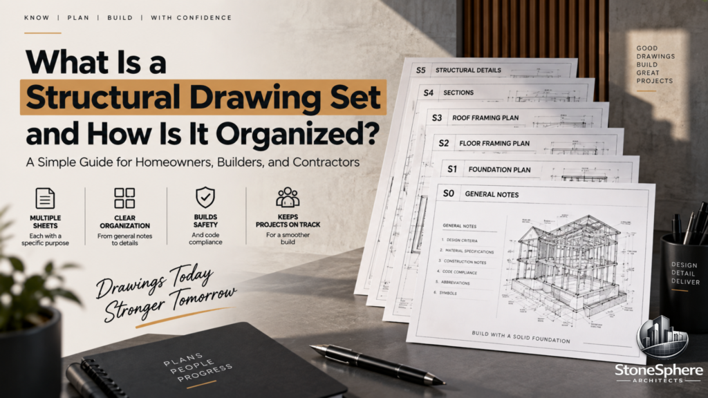
Most complete sets follow a similar pattern, though exact contents vary by project size and building type. A typical structural drawing set includes:
- General notes sheet – design codes, load criteria, and material specifications
- Foundation plan – footing sizes, locations, and reinforcement details
- Framing plans – floor and roof framing layouts, beam and joist sizes
- Sections and details – connection details, wall sections, and typical assemblies
- Schedules – column, beam, and footing schedules summarizing sizes and reinforcement
Larger projects often add separate sheets for retaining walls, stairs, and specialty structural elements.
Read Also: Structural Drawing Checklist: What Should Be Included Before Construction Begins?
How Sheet Numbering Typically Works
Sheet numbering might look arbitrary at first glance, but it actually follows a widely recognized logic across the industry. Most structural drawing set numbering starts with a discipline designator, usually the letter “S,” followed by a series of numbers grouped by category.
A common structure looks like this:
- S0-series – general notes and cover information
- S1 or S2-series – foundation and framing plans by floor level
- S3-series – building sections
- S5 through S9-series – details grouped by element, such as slabs, columns, or beams
- S10-series – stairs and other vertical circulation elements
This grouping approach lets reviewers and contractors jump straight to the section they need without scanning the entire set.
Why Organization Matters as Much as the Design
A technically sound design loses much of its value if the drawing set is confusing to navigate. Clear organization inside a structural drawing set reduces field errors, speeds up plan review, and keeps coordination with architectural and MEP disciplines far smoother.
Consistent sheet numbering also makes it easier to add new sheets later without disrupting the entire sequence. Leaving gaps between numbers, such as jumping from S201 to S210, gives room for future additions without renumbering the whole set.
How Structural Sheets Coordinate With Other Disciplines
Structural drawings rarely stand alone in a full construction submission. They need to align closely with architectural floor plans and MEP layouts, since conflicts between disciplines are far more expensive to catch after construction starts than during design.
Matching grid lines, consistent room and wall labeling, and cross-referenced details between the architectural and structural sets all help avoid these conflicts. Many firms review both sets side by side before submission specifically to catch mismatches early, when they’re still cheap and easy to fix.
Common Mistakes in Structural Drawing Organization
A handful of avoidable issues show up repeatedly in poorly organized sets. Watch for these before finalizing your drawings:
- Inconsistent sheet numbering that doesn’t follow a clear logical order
- Missing cross-references between plans, sections, and details
- Incomplete schedules for columns, beams, or footings
- Mismatched grid lines between structural and architectural sheets
Catching these issues before submission saves significant time during both permit review and construction.
Digital File Naming and Version Control
Beyond sheet numbering, most firms also apply consistent digital file naming conventions that mirror the physical sheet numbers. This keeps electronic files, PDFs, and CAD models organized in a way that matches the printed set exactly, which matters once a project moves into multiple revision rounds.
Version control becomes especially important when structural drawings go through several rounds of comments from a plan reviewer. Tracking revision dates and clouding changed areas on each sheet helps everyone on the project quickly identify what’s new without comparing entire sheets line by line.
Typical Scale and Presentation Standards
Structural sheets generally follow standard scales depending on what they show. Plans and framing layouts are often drawn at 1/8″ or 1/4″ scale, while detail sheets zoom in much closer, sometimes at 1″ scale or larger, to show connections clearly.
Consistent line weights, symbol legends, and text sizing across every sheet also matter more than many people expect. A set that mixes scales or symbol styles between sheets can slow down a reviewer’s ability to interpret details correctly, even when the underlying engineering is accurate. Keeping a shared template across all sheets, rather than letting each drafter set up their own style, is one of the simplest ways to avoid this problem entirely.
Final Thoughts
A well-organized structural drawing set does more than satisfy a building department; it makes construction faster, coordination easier, and errors less likely across every discipline involved. Understanding the standard components, sheet numbering logic, and how structural sheets align with architectural and MEP plans helps ensure your project moves smoothly from design through approval and into the field.