
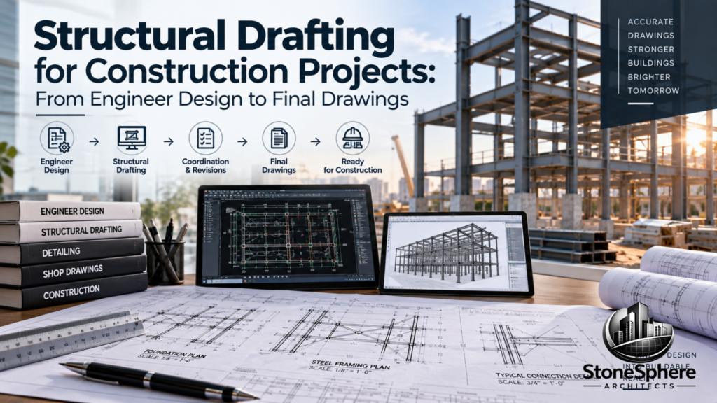
Handing a contractor a folder of engineering calculations instead of clear, buildable drawings is a fast way to bring an entire job site to a standstill. Engineers work in numbers, load paths, and material specifications, but crews need scaled drawings showing exactly where every beam, column, and connection goes. The fix is a clear process: structural drafting for construction takes an engineer’s design and calculations and turns them into coordinated, buildable drawings a crew can actually follow. This article walks through that entire process step by step, from the engineer’s initial design work to the final drawing set that reaches the field.
Where Structural Drafting Fits in the Design Process
Structural drafting sits between architectural design and construction. Once an architect’s plans establish the building’s layout and appearance, a structural engineer reviews them to determine how the building will actually stand up, calculating loads, choosing materials, and sizing key elements like beams, columns, and foundations.
Structural drafting for construction then takes that engineering work and turns it into the detailed, scaled drawings crews use on-site. Architectural drawings show how a building will look; structural drawings show how it will stay standing.
Read Also: Structural vs. Architectural Drawings: Key Differences Explained
Step 1: Engineering Analysis and Load Calculations
Before any drafting begins, the engineer determines what the structure needs to support. This includes identifying live loads, dead loads, wind forces, and seismic considerations based on the building’s location and use.
A site survey often supports this stage too, gathering information about soil conditions and terrain that influence foundation design. These calculations become the technical foundation every drawing that follows is built on.
Step 2: Translating Calculations Into Drawings
With calculations complete, drafters begin converting engineering intent into visual, scaled drawings. This is where structural drafting for construction actually takes shape, typically starting with:
- Foundation plans – footing sizes, depths, and reinforcement layout
- Framing plans – beam, column, and joist placement by floor level
- Elevations and sections – vertical views showing height and internal structure
- Connection details – bolt patterns, welds, and load transfer points
- Reinforcement drawings – rebar sizing, spacing, and bend schedules for concrete
Drafters use CAD or BIM software to keep these drawings precise and easy to update as the design evolves.
Step 3: Coordinating With Other Disciplines
Structural drawings rarely stand alone in a full construction set. During this stage, drafters and engineers adjust layouts to accommodate ductwork, plumbing, and electrical conduits without compromising structural integrity.
This coordination step catches conflicts between disciplines early, when they’re still cheap to resolve, rather than after concrete is poured or steel is set in place.
Read Also: Structural Drawing Coordination: How to Avoid Conflicts Between Disciplines
Step 4: Review and Revisions
No structural drawing set moves to construction without a thorough review. This stage confirms every dimension is accurate, every code requirement is met, and every sheet aligns with the others in the set.
Revisions at this point are normal and expected. Catching an inconsistency between a framing plan and its corresponding section, for example, is far less costly here than discovering it once a contractor is already building from the drawings.
Step 5: Finalizing for Permitting and Construction
Once revisions are resolved, the drawing set moves into its final, permit-ready form. This typically includes a complete title block, revision history, and any required engineer’s stamp confirming the design meets applicable codes.
Read Also: What Is a Structural Drawing Title Block and What Should It Contain?
From here, the drawings support two parallel needs: satisfying the building department’s review requirements and giving contractors a clear, buildable reference for actual construction.
Why This Process Matters
Skipping or rushing any stage of structural drafting for construction increases the risk of costly field errors, code violations, or safety issues. A drawing set that accurately reflects engineering calculations, and that’s been properly coordinated across disciplines, keeps a project moving smoothly from design through completion.
Investing time in each step, rather than compressing the process to save a few days, almost always saves far more time and money once construction is underway.
Tools That Support the Modern Process
Structural drafting has shifted significantly from manual hand-drawn plans to CAD and BIM-based workflows. This shift lets drafters update drawings quickly as designs evolve, and it keeps every sheet automatically consistent when a single change affects multiple views.
BIM in particular supports better coordination, since architectural, structural, and MEP models can be layered together to catch spatial conflicts before construction begins. Some firms are also beginning to explore AI-assisted drafting tools, though human review remains essential for catching the kind of nuanced judgment calls automated tools can still miss, especially on complex or unusual structural conditions.
Common Pitfalls That Slow the Process Down
A handful of recurring issues show up when this process gets rushed or poorly managed. Watch for these along the way:
- Incomplete load calculations carried forward into drafting before they’re finalized
- Missed coordination between structural and MEP layouts
- Skipped review cycles that let small inconsistencies slip into the final set
- Delayed engineer sign-off, holding up the permitting timeline unnecessarily
Catching these issues early keeps the overall timeline predictable and avoids costly rework later in construction. A well-run process treats each step as a checkpoint, not an afterthought, and that discipline pays off once drawings finally reach the field.
Final Thoughts
Structural drafting for construction is the critical link between an engineer’s calculations and a buildable, code-compliant drawing set. Following this process step by step, from initial load analysis through final permitting, keeps design intent intact and gives contractors the clear reference they need to build safely and accurately from start to finish.