
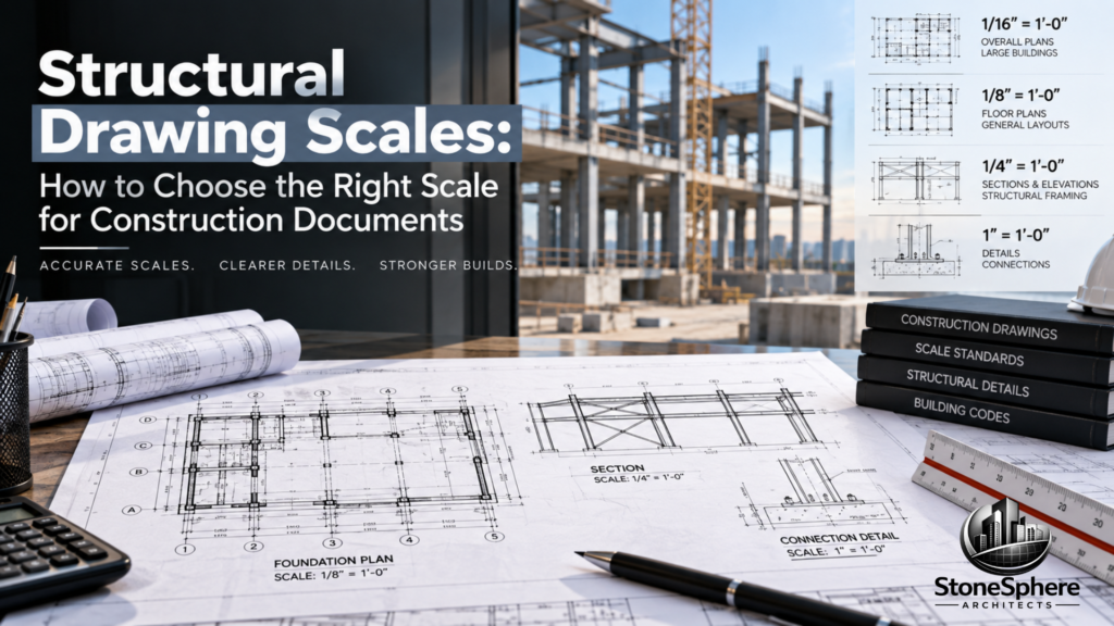
Printing a foundation plan at the wrong scale, or mixing scales across sheets in the same set, is a small mistake that causes big problems once a crew starts measuring directly off a printed drawing. A scale that’s too small hides critical details; one that’s too large wastes paper and clutters simple plans with unnecessary complexity. The fix is straightforward: matching your structural drawing scales to the purpose of each sheet, from broad site plans down to close-up connection details. This article breaks down the standard scales used in structural work, when to use each one, and how to keep an entire drawing set consistent.
What Drawing Scale Actually Means
A drawing scale expresses the ratio between a measurement on paper and the real building. A common structural scale like 1/4″ = 1′-0″ means every quarter inch on the sheet represents one foot in actual construction.
Choosing the right scale balances two competing needs: fitting the whole structure on a standard sheet size while still showing enough detail for the drawing to be useful.
Read Also: Structural Drawing Symbols and Abbreviations: Complete Guide
Getting this balance wrong is one of the most common, avoidable mistakes in a drawing set.
Standard Structural Drawing Scales by Sheet Type
Different sheet types call for different structural drawing scales, and most projects follow a fairly consistent pattern across the industry. Common scales include:
- Site plans – typically 1″ = 20′ or 1″ = 30′, sometimes smaller for large sites
- Foundation and framing plans – usually 1/8″ = 1′-0″ or 1/4″ = 1′-0″
- Building sections – often 1/4″ = 1′-0″, occasionally 1/8″ for larger structures
- Connection details – commonly 1″ = 1′-0″ or 1-1/2″ = 1′-0″ for full clarity
- Full-size details – drawn at 1:1 when precision is critical, like anchor bolt layouts
Metric projects follow a similar logic using ratios like 1:100 for general plans and 1:20 or 1:10 for details.
Why Scale Choice Affects Readability
Picking the wrong structural drawing scales for a given sheet directly hurts how usable the drawing is in the field. A foundation plan drawn too small forces reviewers and contractors to squint at tiny dimensions or miss details entirely.
On the other hand, drawing a simple overall section at an unnecessarily large scale wastes sheet space and can make the drawing harder to follow at a glance. Matching scale to the level of detail needed keeps every sheet clear and efficient to read.
Matching Scale to Sheet Size
Sheet size and scale work together, and choosing one without considering the other often backfires. Larger structures typically need a smaller scale, like 1/8″ = 1′-0″, just to fit on a standard sheet such as 24″ x 36″.
Smaller buildings or individual floor plans can usually use a larger scale, like 1/4″ = 1′-0″, while still fitting comfortably. When a structure is too large even for a smaller scale, splitting the plan across multiple match-lined sheets is the standard solution rather than shrinking the scale further.
Keeping Scale Consistent Across a Drawing Set
Consistency matters as much as choosing the correct scale in the first place.
Read Also: What Is a Structural Drawing Set and How Is It Organized?
Mixing structural drawing scales without clear labeling confuses reviewers and increases the risk of a contractor measuring directly off the wrong sheet.
A few habits help maintain consistency:
- Label the scale clearly on every sheet, near the title block
- Use the same scale for related sheet types throughout the set
- Call out non-standard scales explicitly when a detail needs to break from the norm
- Avoid relying on “not to scale” drawings except when absolutely necessary
Digital Considerations for Scale
CAD and BIM software introduce their own scale considerations, since drawings are often modeled at full size and scaled down only when printed. Setting the correct viewport or plot scale before printing is essential, since an incorrect setting can distort dimensions even when the underlying model is accurate.
Digital plan review tools also rely on correct scale settings to measure directly from a PDF, so confirming scale accuracy before submission protects against errors during both review and construction.
Read Also: How to Convert Structural Engineer Markups Into Construction Documents
Common Scale Mistakes to Avoid
A handful of recurring errors show up across poorly scaled drawing sets. Watch for these before finalizing your documents:
- Printing at the wrong plot scale, distorting dimensions even when the digital model is accurate
- Mixing scales on related sheets without clear labeling near the title block
- Overusing “not to scale” notations instead of committing to an appropriate scale
- Choosing a scale too small for connection details that need precise dimensions
Catching these issues before a set goes out for review or construction saves real time compared to fixing misread dimensions in the field.
Final Thoughts
Choosing the right structural drawing scales comes down to matching each sheet’s purpose to an appropriate level of detail, then keeping that scale consistent and clearly labeled throughout the set. Site plans, framing plans, and connection details all call for different scales, but the underlying goal stays the same: a drawing set that’s clear, accurate, and easy for every reviewer or contractor to read correctly.